A Bridge Rehabilitation Project Example That Holds Up
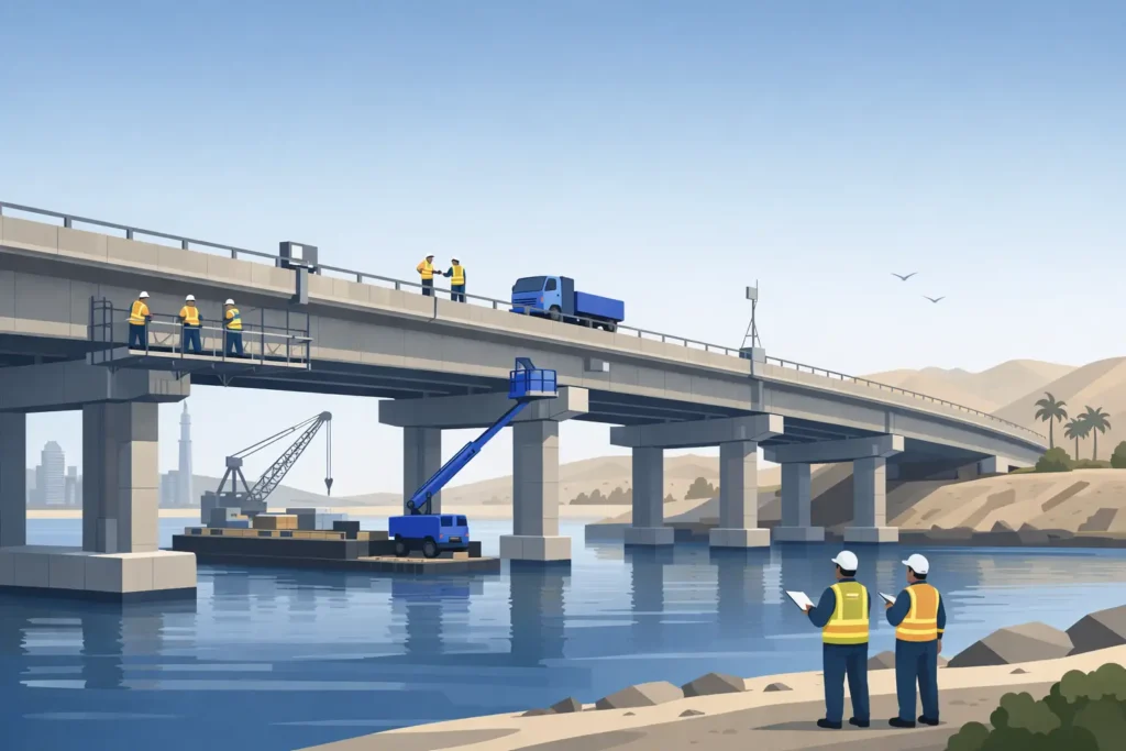
A bridge rehabilitation project example is most useful when it shows the decisions behind the repair, not only the completed concrete and new expansion joints. The following representative case concerns a reinforced concrete highway overbridge carrying increasing freight traffic, with recurring deck leakage, localized spalling, bearing deterioration, and a load-rating question that could not be resolved from record drawings alone.
The asset owner did not need a cosmetic repair package. It needed a defensible basis for keeping the route open, prioritizing capital expenditure, and demonstrating that the rehabilitated structure would perform under its required design life and traffic demand.
Bridge Rehabilitation Project Example: Starting With the Evidence
The structure is a three-span reinforced concrete bridge built in the late 1980s. Its deck is supported on prestressed concrete girders, seated on reinforced concrete piers and abutments. The bridge carries four traffic lanes over a local access road, making full closure commercially and operationally difficult.
Routine inspections had identified longitudinal cracking above the girders, delamination around deck drains, concrete spalls at pier caps, leaking joints, and corrosion staining at several bearing locations. None of these symptoms alone established the governing structural risk. Together, they indicated a probable water-management failure with consequential chloride ingress and corrosion activity.
The first engineering decision was therefore not to specify repair mortar. It was to establish the condition, capacity, and deterioration mechanisms with enough confidence to determine what needed intervention and what could remain in service under monitoring.
A properly scoped investigation combined close visual inspection with hammer sounding, cover-meter surveys, carbonation and chloride sampling, concrete core testing where justified, crack mapping, and survey control of deck levels and bearing lines. Access provisions were planned to inspect soffits, diaphragms, pier caps, bearings, and drainage outlets rather than limiting the work to the deck surface.
Record drawings were reviewed against site measurements. This matters on older bridges: nominal dimensions, reinforcement arrangements, diaphragm details, bearing types, and prior repairs often differ from the available documents. Where uncertainty affects calculated resistance, the engineer should verify it through targeted investigation, not bury it in a blanket assumption.
Condition Does Not Equal Capacity
The inspection found that corrosion-related damage was concentrated at deck drainage paths and expansion joints. Several bearings had restricted movement because of corrosion and debris accumulation. The concrete girders showed isolated cracking but no widespread section loss or distress pattern consistent with global flexural failure.
That distinction shaped the project. The deck and support details required intervention, while the primary girders required confirmation through analysis and monitoring rather than automatic strengthening.
A load rating was completed using verified geometry, material test results, measured reinforcement where available, and realistic dead-load allowances for overlays, barriers, utilities, and prior repairs. The analysis considered the applicable owner requirements and recognized bridge loading provisions, commonly AASHTO LRFD for US assets, alongside the original design basis where relevant. Critical sections included midspan positive-moment regions, girder ends, pier-cap cantilevers, bearing zones, and deck regions affected by wheel loads.
The rating demonstrated adequate capacity for the current legal traffic envelope, subject to localized repair and restoration of bearing function. However, it did not justify unrestricted future increases in permitted truck loading. That is a useful result. Engineering credibility depends on stating both what the bridge can carry and the limits within which that statement remains valid.
Defining the Rehabilitation Scope
The repair strategy was organized around the deterioration mechanism. Water had entered through failed joints and ineffective deck drainage, then traveled to girder ends, bearing shelves, and pier-cap faces. Replacing visible spalls without controlling water would have restarted the same cycle.
The defined scope included removal of delaminated and chloride-contaminated concrete to sound substrate, treatment or replacement of reinforcing steel where section loss exceeded the repair criteria, and reinstatement with a compatible structural repair system. Repair material selection considered bond, shrinkage, elastic modulus, permeability, and application thickness. A high-strength material is not automatically the right material if its stiffness or shrinkage behavior creates a new compatibility problem at the repair interface.
At the deck, the project included localized full-depth repairs, crack treatment where cracks were assessed as nonstructural but water-bearing, waterproofing, and an asphalt overlay compatible with the drainage geometry. Drain outlets were extended and detailed to prevent discharge onto girders, bearings, pier caps, or abutment backwalls.
Bearing works required particular care. Before replacement, the team confirmed actual reactions, movement demands, support geometry, jacking locations, temporary works loads, and the condition of adjacent concrete. Bearing replacement is often presented as a routine maintenance task. On an operating bridge, it is a temporary-works operation with direct structural consequences. Jacking sequences, stroke limits, survey hold points, and traffic restrictions must be designed and inspected as part of the permanent-work package.
Where pier-cap spalls had exposed reinforcement but testing showed limited chloride penetration beyond the immediate repair zone, the owner selected targeted concrete repairs combined with protective coating. Full cathodic protection was evaluated but not adopted. It would have provided a broader corrosion-control measure, but its installation, monitoring obligations, and whole-life cost were not proportionate to the measured extent of contamination. That decision depends on exposure severity, continuity of contamination, access for future repairs, and the owner’s maintenance model.
Design for Construction, Not Only Analysis
The highest-risk point in many bridge rehabilitation projects is the interface between the repair design and the contractor’s sequence. The analysis model may show satisfactory capacity, but that does not guarantee safety during hydrodemolition, deck breakout, lane shifts, jacking, or staged overlay placement.
The construction package therefore defined repair extents, breakout boundaries, reinforcement splice requirements, surface-preparation standards, curing requirements, and acceptance criteria. It also identified no-breakout zones near prestressing strands and critical girder regions. Any unexpected reinforcement configuration, tendon duct, void, or extent of deterioration triggered an engineering hold point before the contractor proceeded.
Traffic management was phased to retain two lanes in each direction during peak hours. Deck works were sequenced by lane, with waterproofing and overlay operations planned to avoid leaving exposed repair areas vulnerable to rain or traffic-induced damage. The approach reduced network disruption, though it extended construction duration and required tighter quality control at stage interfaces.
Detailed drawings carried the same importance as calculations. They showed drainage falls, joint interfaces, bearing access clearances, repair boundaries, bar replacement details, temporary support requirements, and inspection locations. For infrastructure contractors, these are not secondary production documents. They are the instructions that convert engineering intent into installed work.
Quality Control and Measurable Acceptance
Rehabilitation succeeds or fails at the substrate and interface. The owner’s specification required verification of concrete removal depth, reinforcement cleaning, continuity of bars, substrate profile, moisture condition, repair material batching, placement, curing, and final cover. Pull-off testing, sounding, repair material strength tests, and drainage tests were used where applicable.
Survey checks were completed before and after bearing work to confirm that jacking had not introduced unintended rotations or settlements. Joint gaps and bearing alignment were verified at the prevailing installation temperature, with the thermal movement range considered in the final setting.
A photographic record and repair location schedule were maintained throughout construction. This creates a baseline for later inspections and avoids the familiar problem of future teams encountering a repaired area with no record of what was removed, replaced, or concealed.
Monitoring After Return to Service
The bridge reopened with its immediate defects addressed, drainage restored, and load-rating basis documented. The rehabilitation did not eliminate the need for asset management. It converted an uncertain asset into one with known condition, defined performance limits, and a prioritized inspection plan.
The owner adopted close follow-up inspections after the first wet season, then returned to a risk-based interval once drainage and repairs had demonstrated satisfactory performance. Crack gauges at selected locations and periodic bearing inspections were retained because they offered a low-cost check on the assumptions made during assessment.
For structures with heavier freight demand, known fatigue concerns, or evidence of progressive movement, structural health monitoring may be justified. The case for instrumentation should be tied to a specific decision: confirming strain demand, detecting abnormal movement, validating a load restriction, or targeting inspections. Monitoring without defined thresholds and actions is data collection, not asset control.
The practical lesson from this bridge rehabilitation project example is simple: repair scope should follow the failure mechanism, and every major intervention should be traceable to inspection evidence, calculation, constructability review, and measurable acceptance. When those elements are coordinated, the owner receives more than a repaired bridge. It receives a documented basis for operating, maintaining, and funding the asset with confidence.