Steel Connection Finite Element Analysis
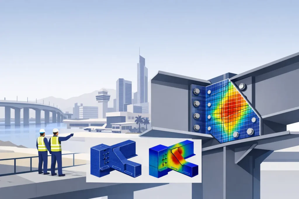
A connection can satisfy simplified member-force checks and still create an unacceptable local condition at a column face, weld toe, bolt group, or plate edge. Steel connection finite element analysis is used where the load path is three-dimensional, the geometry is irregular, or force redistribution cannot be represented credibly by conventional component checks alone. For transfer structures, heavily loaded moment joints, bridge details, crane supports, and architecturally exposed steel, it provides the evidence needed before steel reaches the fabrication shop.
When Steel Connection Finite Element Analysis Is Required
Finite element analysis is not a replacement for standard connection design. Simple shear tabs, conventional end plates, and routine bracing connections are normally more efficiently designed using recognized code procedures and clear hand-check calculations. The analysis becomes proportionate when connection behavior is governed by interaction rather than a single, easily isolated resistance mechanism.
Typical triggers include non-orthogonal framing, deep transfer girders framing into built-up columns, eccentric beam reactions, thick plate assemblies, large tubular nodes, and moment connections subjected to combined axial load, shear, bending, and torsion. The same applies where architectural restrictions limit plate dimensions or where equipment loads introduce fatigue-sensitive stress ranges.
A detailed model is also justified when the connection is central to a high-consequence load path. In an airport canopy, industrial platform, bridge diaphragm, or long-span roof, local connection flexibility can alter global force distribution. The issue is not only whether the joint remains safe at ultimate load. It is whether its stiffness, rotation capacity, and fabrication arrangement support the structural behavior assumed by the overall design model.
Start With the Design Question, Not the Software
An analysis model is only defensible when it is built to answer a defined engineering question. Before modeling, the engineer should establish the governing load combinations, member forces, support assumptions, applicable design standard, required performance criteria, and the intended limit states.
For projects designed to AISC provisions, Eurocode 3, British Standards, AASHTO, or a project-specific authority basis, the finite element model must align with the governing resistance framework. Material strength factors, load factors, weld criteria, bolt behavior, and serviceability limits cannot be selected independently of the project code. Where more than one standard is used, the design basis must state which provisions govern each check.
The critical question may be local yielding of a column flange, prying in an extended end plate, stress concentration at a cope, or whether a stiffener arrangement develops the assumed panel-zone resistance. Different questions require different model fidelity. A highly detailed bolt thread model is rarely useful if the real uncertainty is rotational restraint provided by the supporting member.
Modeling the Load Path
Connection models should represent the physical route by which load enters, crosses, and leaves the joint. This sounds straightforward, but errors often begin with idealized restraints. Fully fixing a column end that is flexible in the actual frame can force artificial stress into the connection. Conversely, applying beam-end forces directly to a plate may omit the local effects produced by flange and web load introduction.
Shell elements are generally suitable for plates, column flanges, beam webs, stiffeners, and hollow structural sections where through-thickness stress is not the governing concern. Solid elements can be appropriate around highly confined regions, thick bearing blocks, cast nodes, or complex weld transitions. The choice should be driven by expected behavior, not by a preference for a more visually detailed model.
Bolt modeling deserves particular discipline. Bolts may be represented as simplified connectors, beam elements, contact-supported shanks, or detailed solids, depending on whether the check concerns bolt force, slip, bearing, prying, or local plate deformation. Pretension, friction, hole clearance, and contact conditions materially affect results in slip-critical or fatigue-sensitive joints. Assumptions must be stated, since a nominally rigid bolt representation can conceal load redistribution between fasteners.
Welds should be assessed as part of the force path, not added as a final annotation after analysis. In many complex joints, the governing issue is the combined demand at a weld group caused by local plate bending and eccentricity. Where peak elastic stress appears at a weld termination, the engineer must distinguish a numerical singularity from a meaningful fatigue or fracture risk. Mesh refinement alone does not make that judgment.
Contact, Nonlinearity, and Real Behavior
Steel connections often involve separation, bearing, friction, and changing stiffness under load. Linear elastic analysis can be appropriate for identifying elastic force flow and relative stiffness, but it may be inadequate where contact opens and closes, plates undergo significant local bending, or bolt-hole bearing controls.
Geometric nonlinearity should be considered where deformation changes the load path. Material nonlinearity may be needed to demonstrate ductility, redistribution, or local yielding capacity. Contact nonlinearity is relevant where plates bear against each other, bolts engage hole edges, or compression-only interfaces transfer force.
These enhancements increase analysis time and introduce additional assumptions. They should therefore be used selectively and verified carefully. A nonlinear result is not automatically more reliable than a linear result. Its value depends on credible material data, boundary conditions, contact definitions, and convergence performance.
Reading Results Without Chasing Red Contours
Color plots are useful for locating behavior, but they are not design checks by themselves. A stress contour with a red peak at a re-entrant corner, point load, or weld edge may represent a mathematical singularity. The practical task is to assess stress over a meaningful evaluation path or area, then compare that demand with the relevant limit state.
Model verification should include reaction balance, deformation shape, load transfer through each component, mesh sensitivity, and comparison with independent calculations. If a connection is expected to act as a moment joint, the deformed shape should show a credible tension-compression couple through the beam flanges, column components, bolts, and plates. If the model instead transfers most moment through an unintended restraint, its apparent capacity has little engineering value.
Mesh convergence is particularly important around bolt groups, plate openings, stiffener terminations, and weld-adjacent regions. Refining the mesh should stabilize the quantities used for design, such as bolt force, plate strain, bearing pressure, or averaged stress. It is not necessary for every nodal peak to converge, especially at idealized sharp corners.
The final assessment should separate strength from serviceability. A joint may satisfy ultimate resistance while rotating more than the global model permits, causing facade distress, deck misalignment, equipment vibration, or excessive secondary force in adjacent members. Connection stiffness is often the missing link between a satisfactory local check and a satisfactory structure.
From Analysis to Fabrication-Ready Detail
A finite element model proves little if the final shop drawing cannot be fabricated, welded, inspected, and erected as analyzed. Plate thicknesses, cope clearances, weld access, bolt installation direction, tolerances, drainage, protective coating requirements, and site splice sequence must be resolved in the issued detail.
This is where connection engineering and detailing must remain connected. Adding a stiffener may reduce plate stress but prevent access for a required weld. Increasing plate thickness may solve a local bending check while creating an impractical weld preparation. Moving a bolt line may improve prying behavior but conflict with erection clearance or member edge distance. The preferred solution is the one that is safe, code-compliant, inspectable, and buildable.
For authority submissions and independent review, the calculation package should identify the model scope, software version, element strategy, material properties, load cases, combinations, restraints, contacts, mesh checks, result interpretation, and code verification. Drawings should reference the same connection geometry and revision. Traceability is essential when a joint supports a critical asset or departs from standard details.
The Value of an Independent Technical Check
Complex connection analysis benefits from a review by engineers who understand both global structural behavior and fabrication constraints. The review should challenge the assumed force envelope, restraint conditions, and failure modes before focusing on contour plots. It should also confirm that the connection detail issued to the fabricator matches the analyzed condition.
Engineering Support Group applies this approach to complex steel joints as part of integrated structural analysis, connection design, and fabrication-ready detailing. The objective is not to produce a sophisticated model for its own sake. It is to establish a connection that can be checked, built, inspected, and defended under the governing load cases.
Once a joint is resolved, the fabrication drawings still have to be produced on the construction programme, and additional fabrication detailing capacity can absorb that peak without diluting connection design responsibility.
When a joint carries exceptional force or governs the reliability of a larger structure, the right finite element analysis is a controlled design decision: specific in scope, verified against engineering fundamentals, and carried through to the final detail.