Airport Terminal Structural Design That Performs
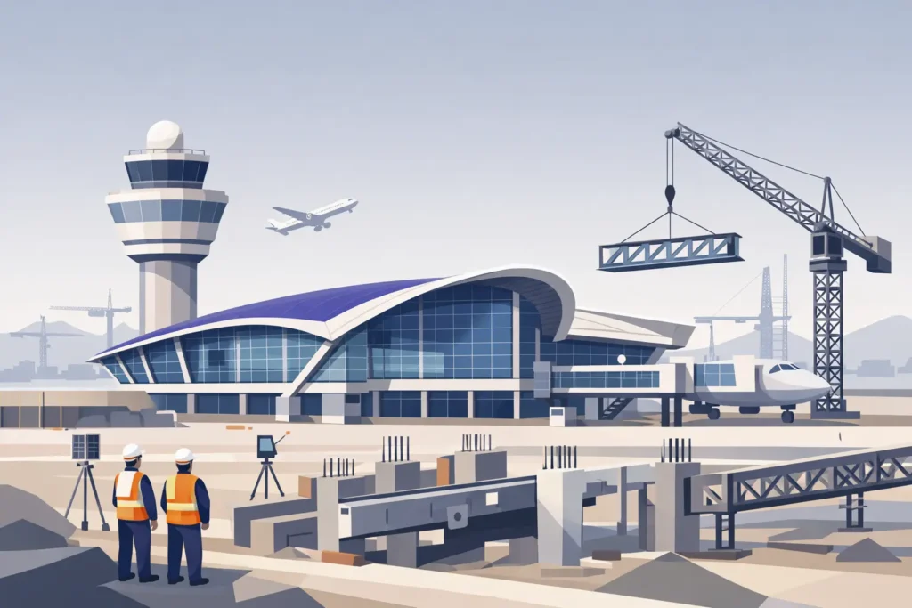
A terminal roof is not simply a large-span architectural gesture. It is a primary operating asset carrying wind, thermal movement, suspended services, maintenance access, signage, baggage interfaces, and often future expansion demands. Airport terminal structural design must therefore be proven beyond the standard building load path. The structure has to support passenger flow, protect critical operations, accommodate intensive building services, and remain inspectable and maintainable over decades of continuous use.
For owners, authorities, architects, and contractors, the central question is not whether a concept can stand. It is whether it can be fabricated accurately, erected around active airside operations, coordinated with MEP systems, and adapted without creating a long-term liability.
Airport terminal structural design starts with operations
Terminal planning determines structural logic earlier than many projects acknowledge. Passenger processing, check-in halls, security screening, baggage handling, retail zones, lounges, gate hold rooms, and boarding bridges each impose different column grids, floor loading, vibration limits, and servicing requirements. A structural scheme that works neatly on a typical floor plan can become inefficient once conveyor routes, plant rooms, vertical transportation, and fire compartments are fully developed.
The most effective approach is to establish the operational geometry before fixing the primary frame. This includes aircraft stand locations, curbside access, departures and arrivals segregation, baggage system routes, service corridors, and the likely position of future concourses. Clear spans may be required above check-in and departure halls, while closer column spacing may be acceptable in back-of-house zones where it supports economical floor construction.
It depends on the terminal type. A regional terminal may prioritize rapid construction and straightforward maintainability. A major hub may justify complex long-span steel, composite, or post-tensioned systems to preserve flexibility in high-volume public spaces. Neither solution is automatically superior. The decision must be based on operational need, lifecycle cost, local fabrication capacity, and the construction sequence.
Long spans need a complete load-path strategy
Long-span roofs are often the defining structural feature of terminal architecture. Steel trusses, plate girders, space frames, diagrids, and composite systems can create broad column-free halls, but each system introduces specific demands for stability, deflection control, connection design, fire protection, and erection tolerances.
The governing design issue is frequently serviceability rather than ultimate strength. Roof deflection can disrupt curtain wall interfaces, drainage falls, ceiling systems, and smoke-control elements. Differential movement between a long-span roof and adjacent concrete cores or lower-level frames must be considered explicitly. Temperature variation can also generate significant movement in exposed Gulf conditions, particularly where roof geometry and solar gain create uneven thermal response.
A defensible analysis should establish gravity, wind, seismic where applicable, thermal, construction-stage, and accidental load cases. Wind effects require particular care around deep roof edges, canopies, façade transitions, and high-level plant enclosures. Local suction pressures can govern cladding support members and connection details even where the global frame remains lightly utilized.
Connections deserve the same level of engineering attention as the primary members. A visually simple roof may transfer substantial axial force, shear, and moment through a limited number of nodes. For irregular geometry or heavily loaded steel joints, finite element analysis of the connection zone may be necessary to verify plate behavior, bolt group demand, weld design, and local buckling resistance. The connection must also be buildable, inspectable, and tolerant of real site geometry.
Movement joints are operational decisions
Expansion joints cannot be placed only where the structural model is convenient. Their locations affect waterproofing, ceilings, fire stopping, passenger routes, baggage conveyors, and MEP distribution. A joint passing through a baggage screening area or a high-specification retail zone can create a costly coordination problem.
Joint strategy should be agreed with architecture, MEP, baggage specialists, and façade designers while the structural concept is still adjustable. The target is controlled movement with maintainable interfaces, not simply a compliant calculation model.
Floors, vibration, and concentrated equipment loads
Terminal floors carry more than people. Baggage handling systems, automated screening equipment, X-ray machines, raised floors, mobile equipment, retail fit-outs, and maintenance vehicles can create concentrated or dynamic loading that exceeds typical commercial building assumptions. Plant replacement routes also matter. A floor that supports an installed unit may not safely support its removal path years later.
Vibration performance requires early review in areas with long floor spans, lightweight construction, passenger bridges, and sensitive screening or communications equipment. Code compliance alone may not provide acceptable operational behavior. Frequency response, damping assumptions, equipment manufacturer criteria, and pedestrian-induced vibration should be considered where relevant.
For concrete frames, post-tensioned slabs can reduce depth and improve span efficiency, but they require disciplined detailing around penetrations, openings, tendon zones, and future coring. For composite steel floors, coordination of deck direction, shear studs, edge beams, and fire protection must be resolved before fabrication. In both cases, the structural model should be aligned with the actual construction sequence, not an idealized final-state condition.
Structure and MEP coordination cannot be deferred
Airports are service-intensive buildings. HVAC ductwork, smoke extraction, electrical containment, fire protection, drainage, communications, security, and airport systems compete for limited ceiling and riser space. Where structural depth is significant, poor coordination quickly becomes visible in lowered ceilings, unplanned openings, congested plant rooms, and site modifications.
BIM coordination provides value when the model is used to make decisions, not merely identify clashes after the frame has been fixed. Structural zones should be established for major ducts, cable trays, sprinkler mains, and access paths. Penetrations through beams, walls, and slabs need a controlled approval process, with opening sizes, reinforcement requirements, and fire-stopping interfaces recorded in the coordinated model and drawings.
This is particularly important in transfer structures, deep beams, trusses, and post-tensioned slabs, where late openings may compromise capacity or require disruptive strengthening. ESG applies structural and BIM capability from its UAE office alongside electromechanical consultancy from its Kuwait office, enabling coordination to be tested against both structural demand and service routing before it becomes a site issue.
Design for phasing, resilience, and asset life
Many terminals expand while remaining operational. Phased construction changes the engineering problem. Temporary conditions, partial load paths, interface points between new and existing structures, and restricted access can govern the practical solution. Construction-stage analysis should verify stability at each significant erection sequence, especially where long-span steel, transfer elements, or temporary works are involved.
Existing terminal extensions also require disciplined investigation. Original drawings may be incomplete, reinforcement may differ from record information, and prior alterations may have changed load paths. Site inspection, material testing, scanning, selective opening-up, and load assessment should establish the condition of the asset before new loads are introduced. ISO 13822 principles provide a useful framework for assessing existing structures where evidence is incomplete or deterioration is present.
Resilience should be defined in project-specific terms. It may mean progressive collapse resistance, accidental vehicle impact protection at curbside areas, blast-informed façade and structural response, flood protection for critical rooms, or redundancy in roof support systems. ICAO requirements, local authority regulations, fire and life-safety strategy, and the owner’s business-continuity objectives must be considered together.
Durability is equally operational. Corrosion exposure, condensation risk, roof drainage, joint leakage, inaccessible steelwork, and the maintainability of protective coatings all influence lifecycle cost. A terminal cannot be treated like a building that can close for extended remedial works. Details should permit inspection, drainage, replacement of sacrificial components, and localized repair without disrupting passenger operations.
Detail for fabrication and authority review
A terminal structure is delivered through drawings, models, specifications, inspections, and approvals. The design intent must survive this chain without ambiguity. Structural shop drawings should identify member marks, connection geometry, welds, bolts, camber requirements, splice locations, reinforcing congestion, embedded items, and interfaces with architectural and MEP packages.
For reinforced concrete, bar bending schedules and constructible reinforcement layouts are essential around heavily loaded columns, transfer beams, cores, openings, and foundation zones. For structural steel, fabrication tolerances, site splice strategy, lifting points, and erection stability must be coordinated before release. These are not drafting details. They are the point at which analytical intent becomes a buildable asset.
Airport terminal structural design succeeds when the frame supports operations as reliably as it supports load. The right scheme is the one that gives the owner clear expansion options, gives the contractor controlled interfaces, and gives the reviewing authority calculations and details that remain defensible through every load case.