MEP Riser Coordination for Buildable Towers
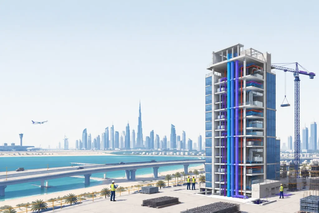
A riser shaft can appear adequately sized on a typical floor plan and still fail at the point where it matters most: the transfer floor, plant level, podium interface, or basement connection. MEP riser coordination is therefore not a routine clash exercise. It is a controlled design process that establishes whether vertical services can be installed, inspected, firestopped, supported, and maintained within the building geometry approved for construction.
For towers, hospitals, hotels, mixed-use developments, and institutional facilities, a poorly resolved riser concentrates risk in a small footprint. The resulting changes can affect architectural layouts, structural openings, slab edge reinforcement, fire compartmentation, procurement, and trade sequencing. Once concrete work has progressed, a nominally minor shaft adjustment becomes a cost, program, and authority compliance issue.
Why MEP riser coordination needs early control
A riser is a three-dimensional route, not a series of isolated floor plan symbols. Every vertical system has its own spatial and operational requirements. HVAC ducts require allowance for insulation, flanges, access doors, and pressure losses at offsets. Plumbing stacks require gradients where branches connect, cleanouts, expansion allowances, and acoustic treatment. Electrical containment requires separation, bend radii, cable pulling access, and clear identification. Fire protection piping requires valves, testing provisions, seismic restraint where applicable, and coordinated penetration sealing.
The available shaft area is further reduced by structural walls, beams, transfer elements, slab openings, fire-rated enclosures, access doors, and the practical working space required to install the systems. A model that only proves that objects do not overlap is not sufficient. It must demonstrate that each service can be assembled in the correct order and subsequently accessed without opening finished walls or removing another trade’s work.
The critical locations are rarely typical floors alone. They include where ductwork changes orientation, where drainage systems combine, where busduct enters an electrical room, where smoke extract connects to a fan room, and where services cross movement joints. Plant room interfaces deserve the same scrutiny. A shaft can be coordinated through twenty floors and still be unbuildable at its roof termination.
Establish the riser design basis before modeling
Effective coordination begins with a documented basis of design. The project team should agree the systems assigned to each shaft, the design flow or load basis, likely future capacity requirements, enclosure ratings, access strategy, and responsibility for penetrations and supports. This is particularly important where architecture, structure, and MEP design are being developed by separate parties.
The first model review should test gross shaft capacity, not attempt to resolve every fitting. Each discipline needs to model the real spatial envelope rather than a centerline representation. That means including insulation thicknesses, duct flanges, valves, access zones, cable tray depths, support zones, and required clearances. Where manufacturer information is not yet fixed, conservative allowances should be stated and recorded as design assumptions.
Model level of development must match the decision being made. At an early design stage, a coordinated spatial reservation may be appropriate. Before issued-for-construction documentation, the riser should be developed to a level where offsets, branch connections, sleeves, access panels, and support requirements can be verified. For remote BIM delivery, the exchange requirements should define model coordinates, shared parameters, approved software versions, IFC needs, file issue protocols, and clash classification rules. A federated model with undefined ownership creates activity, not accountability.
Assign a hierarchy, not just a trade order
There is no universal rule that one MEP service always takes priority. The hierarchy depends on the building type, shaft geometry, fire strategy, and installation sequence. Large, rigid ducts may need the most direct path. Gravity drainage may control because it cannot be freely rerouted without affecting invert levels. Electrical busduct may require protected, dedicated space. Fire mains must remain operable and accessible.
The team should set the hierarchy by reviewing constraints rather than relying on a generic trade sequence. In a hospital, redundancy and maintainability may justify larger protected electrical and medical service zones. In a residential tower, drainage stack alignment and bathroom module repetition may be the governing geometry. In a high-rise with large air systems, duct offsets at mechanical floors can dictate the entire shaft arrangement.
Coordinate structure, architecture, and fire protection together
Riser coordination is often described as an MEP task, but the decisive constraints commonly sit outside MEP scope. Structural walls can limit opening locations. Deep beams and transfer slabs can force service offsets. Core wall coupling beams may leave no acceptable route for large ducts. Post-tensioned slabs introduce strict controls on penetration locations and any later drilling. These conditions must be resolved with the structural engineer before sleeves are cast or reinforcement is detailed.
Openings should be shown as controlled structural information, with dimensions, edge distances, trimming requirements where needed, and a clear statement of whether the opening is cast-in or formed after structural review. The coordination model should also identify builder’s work openings that require fire-rated sleeves or proprietary penetration systems. A penetration is not complete when the pipe or cable tray passes through the wall. It is complete when the rated assembly, support arrangement, and inspection responsibility are defined.
Architectural coordination is equally consequential. Access doors must be large enough and positioned so that valves, dampers, cleanouts, and electrical equipment can be reached. A riser wall may satisfy the fire rating on drawings but become noncompliant if access panels, latches, and penetrations have not been specified as part of the tested system. Finishes, ceiling interfaces, and corridor clearances should be reviewed before the riser is closed.
Use clash detection as a decision system
Navisworks or similar coordination platforms can identify thousands of hard clashes within a federation. The value lies in filtering those results into decisions that affect construction. Duplicate clashes, intended intersections, and low-consequence tolerances should not obscure critical issues such as blocked access, insufficient installation space, unapproved structural penetrations, or conflicting fire compartment lines.
A disciplined issue register should identify the location, systems involved, responsible party, required action, decision deadline, and closure evidence. Screenshots are useful, but they should be supported by revised model views and coordinated drawings. An issue is not closed because it has been marked resolved in a meeting. It is closed when the revised geometry, affected drawings, and construction implications have been checked.
Tolerance management is central to this review. Models are exact; construction is not. Coordination should allow for fabrication tolerances, hanger adjustment, duct flange depth, insulation compression limits, sleeve installation variance, and the ability to maneuver components into place. A nominal 25 mm clearance may avoid a digital clash while offering no practical installation allowance. The acceptable tolerance depends on the service and project execution method, but it should be agreed deliberately rather than left to field improvisation.
Test the construction sequence
The final riser arrangement must be physically installable. This requires a sequence review with the main contractor and specialist subcontractors. A large duct installed after cable trays, or a pipe header installed after shaft walls are closed, may be impossible even when the final modeled arrangement fits.
The review should confirm access from each floor, lifting or handling routes, the order of major service installation, hanger fixing locations, firestopping hold points, and inspection access. Where a riser is congested, prefabricated multi-service modules may reduce site work and improve repeatability. They also demand earlier dimensional certainty and stricter control of slab openings, embeds, and delivery tolerances. Prefabrication is not automatically the best solution, but it is often valuable where floor plates repeat and site access is restricted.
Deliver drawings that the site team can use
A coordinated model must translate into controlled deliverables. Riser elevations, enlarged plans, sections at critical offsets, sleeve schedules, penetration registers, and discipline-specific shop drawings should all carry the same approved geometry. The contractor’s drawing office needs information that can be submitted, fabricated, and installed, not an attractive model that leaves dimensions to interpretation.
Each drawing should make the construction decision visible. Show shaft internal dimensions, service offsets, elevations, pipe sizes, duct sizes, access requirements, fire-rated boundaries, structural opening references, and relevant coordination notes. Where the project uses a client title block and submission workflow, the deliverables should be issued in that format from the outset. This protects traceability through technical review, authority comments, and revision control.
For complex projects, MEP riser coordination should be treated as a gateway before core walls close and before repetitive floor construction locks in an error. The best result is not the riser with the fewest model clashes. It is the riser that remains buildable, maintainable, fire-safe, and defensible when the site team begins installation.